10 ways Russia's Su-57 fighter jet reduces infrared signature

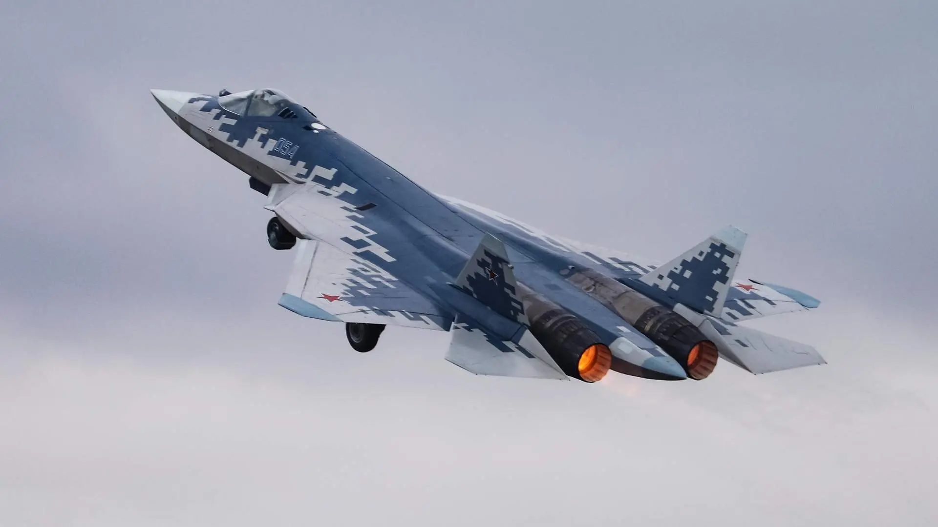
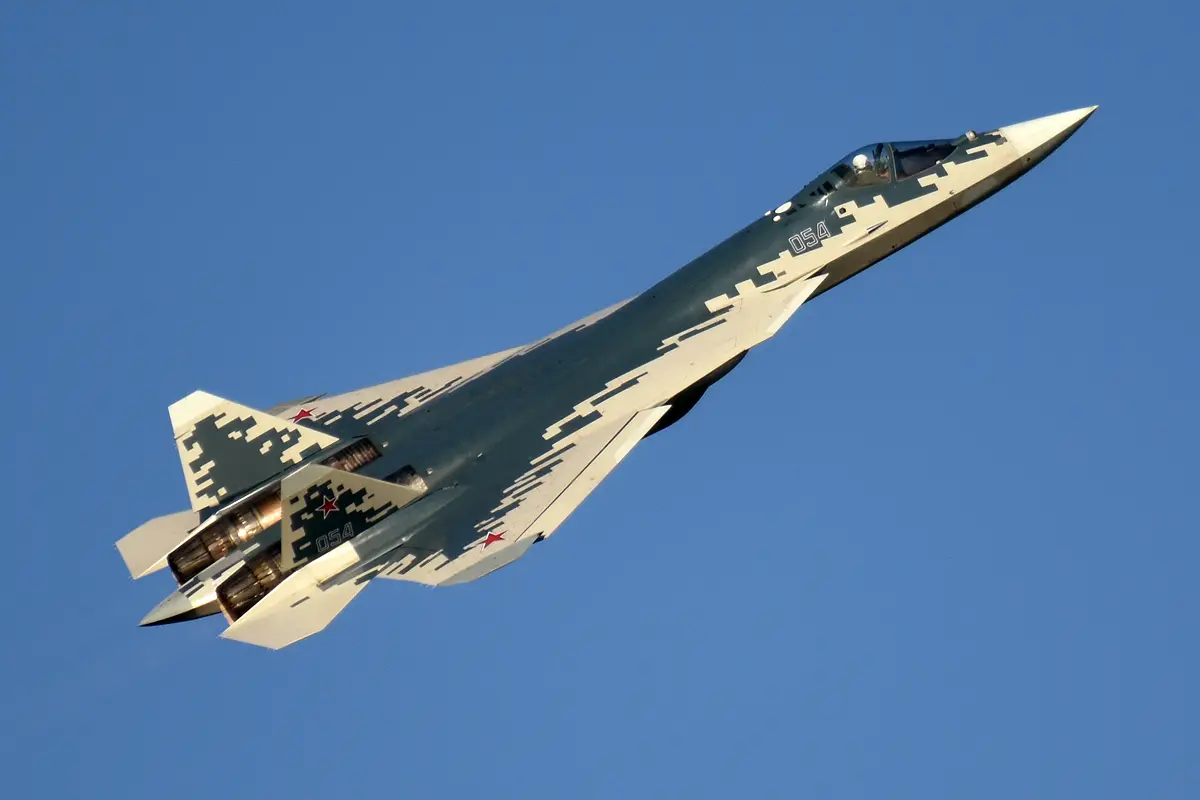
Su-57 reduces infrared signature through 3D nozzle vectoring, serpentine inlets, engine shielding, thermal radiator surfaces, composite materials, internal weapons storage, fuselage positioning, landing gear coverage, bypass air circulation, exhaust plume management.
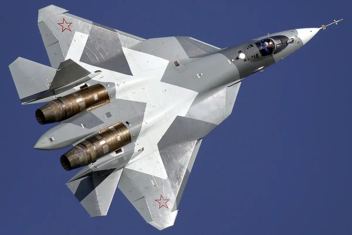
3D Vectoring Nozzles - Hot Exhaust Temperature Reduction
Su-57 features 3D vectoring nozzles mixing hot engine exhaust with cooler bypass air. Temperature reduction achieved through engineered mixing process lowering infrared signature. Nozzle geometry designed for low-altitude flight evading infrared detection. Advanced vectoring enables sustained infrared suppression throughout operational envelope.
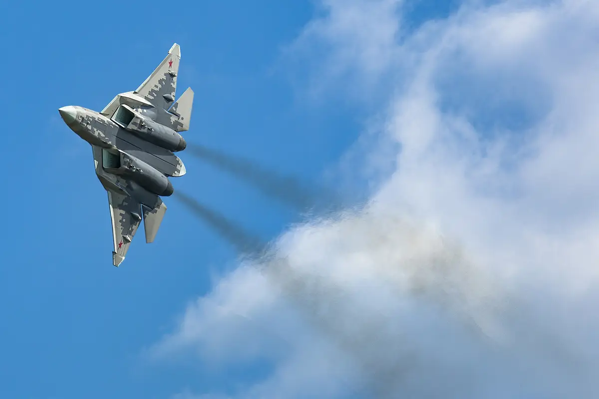
Serpentine Engine Inlets - Thermal Radiation Blocking
Engine inlet design incorporates serpentine ducting preventing direct thermal radiation paths. S-shaped intake configuration shields combustor heat from forward-aspect thermal seeker sensors. Inlet geometry directs cooler boundary layer air across hot surfaces. Design reduces infrared signature significantly during cruise flight.
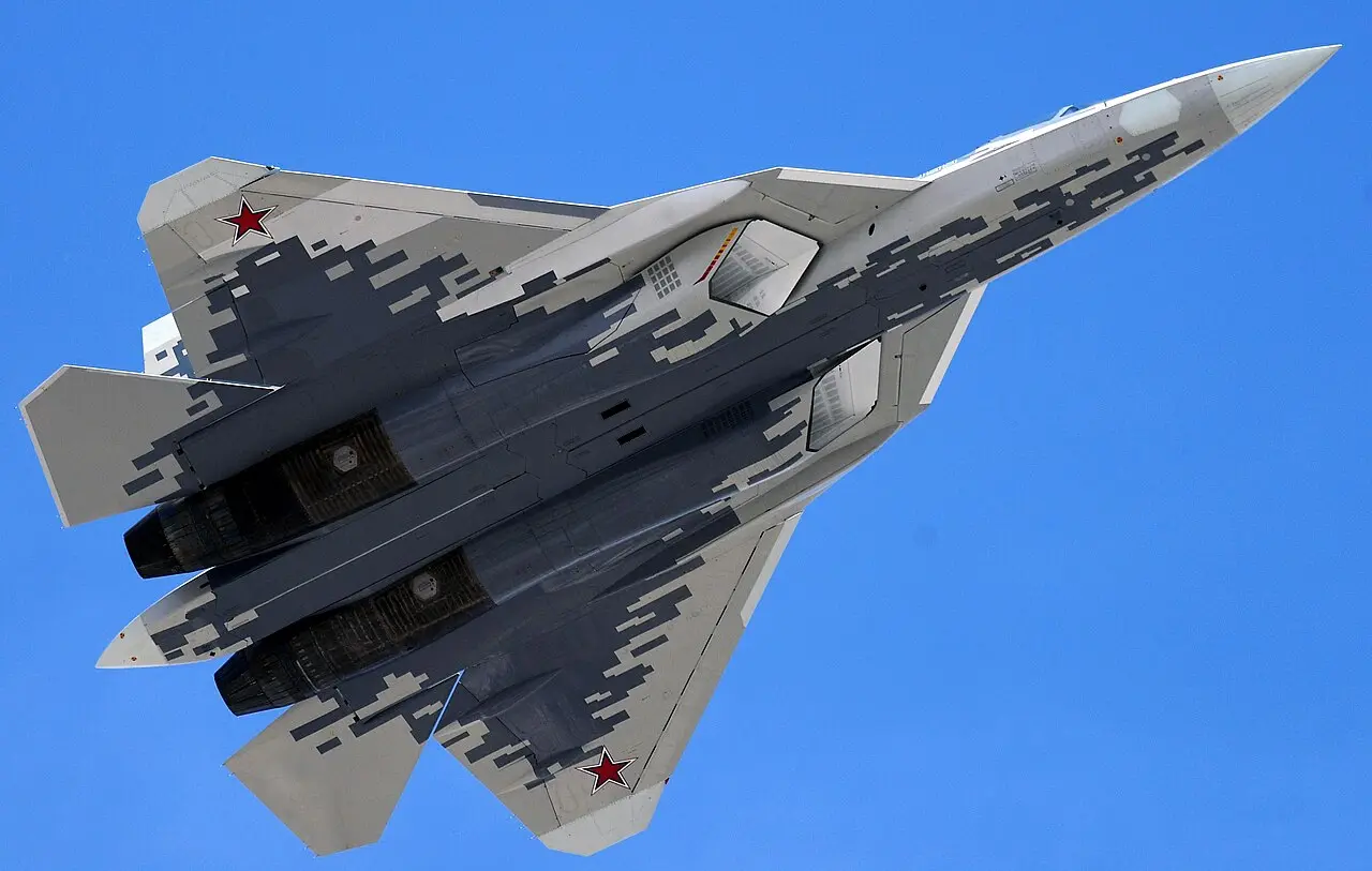
Integrated Engine Shielding - Fuselage Heat Isolation
Su-57 positions engines within fuselage shielded by structural materials and thermal barriers. Composite materials surrounding engine compartment absorb and distribute radiated heat. Heat dispersal across airframe reduces peak temperature concentration. Shielding design prevents direct infrared emission toward threat seeker systems.
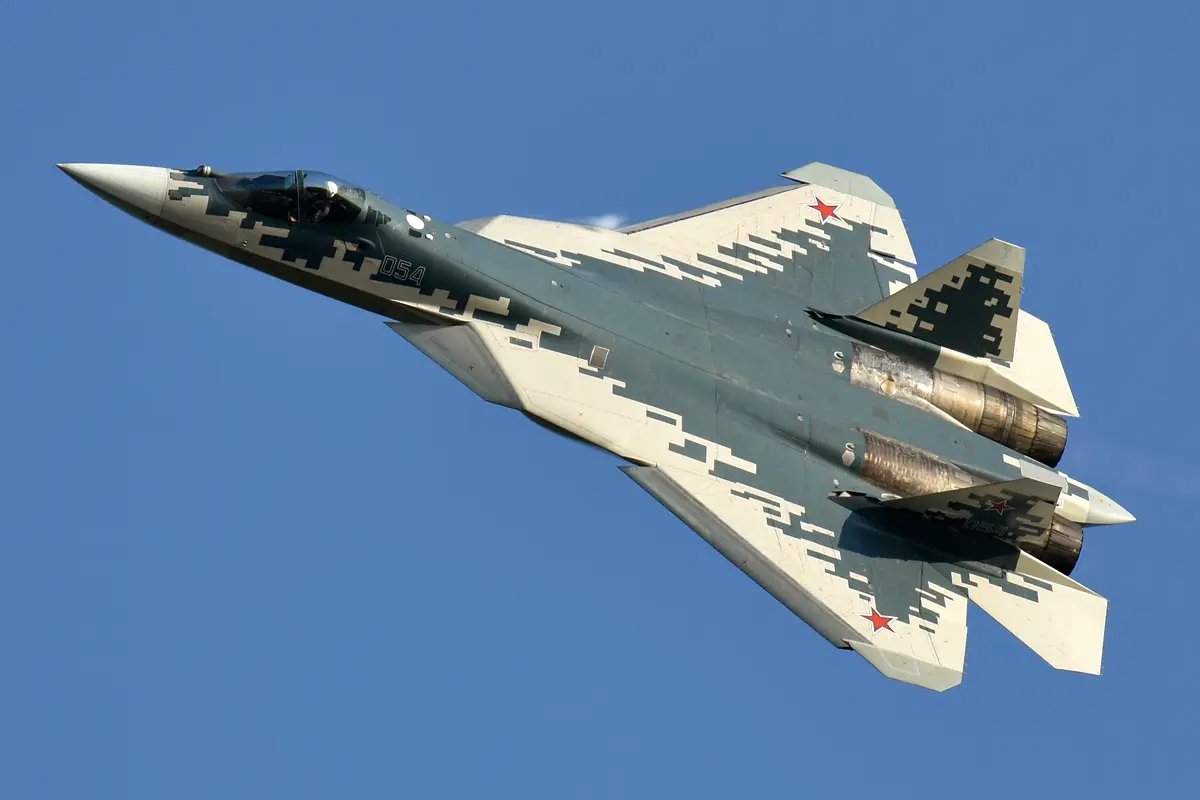
Thermal Radiator Surfaces - Distributed Heat Management
Fuselage design includes thermal radiator panels distributing engine heat across larger areas. Distributed heating reduces peak temperature preventing concentrated infrared signature. Panel positioning optimised for heat dissipation while maintaining aerodynamic efficiency. Radiator surfaces minimise detectable temperature differential.
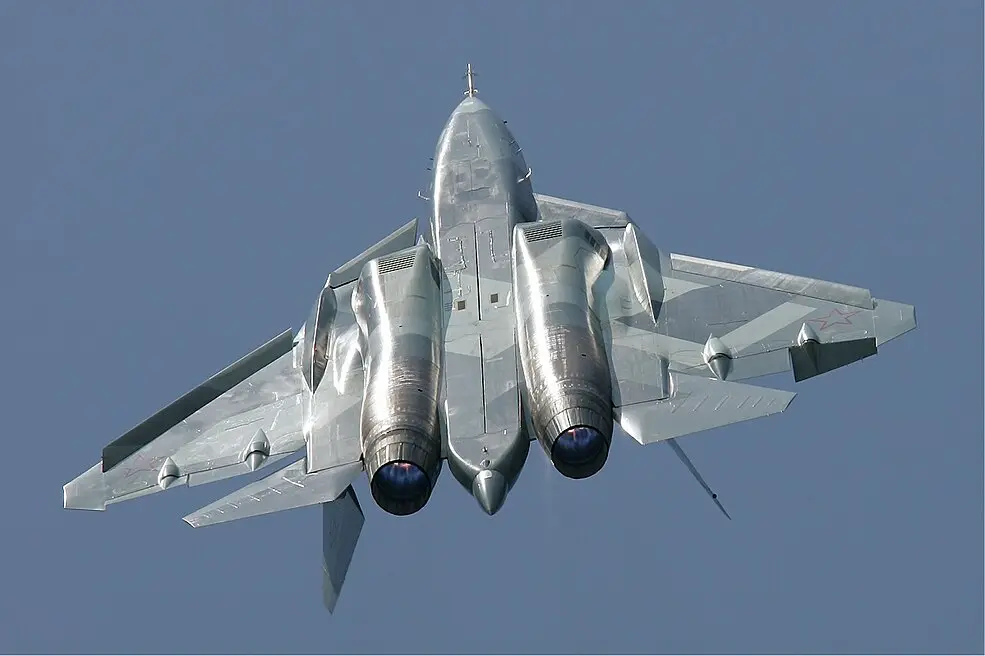
Composite Material Properties - Reduced Thermal Emissivity
Advanced composites reduce thermal emissivity compared to conventional aluminium structures. Lower emissivity decreases infrared radiation at given surface temperatures. Composite airframe distributes heat more uniformly reducing hot spots. Material selection balances thermal performance with structural requirements.
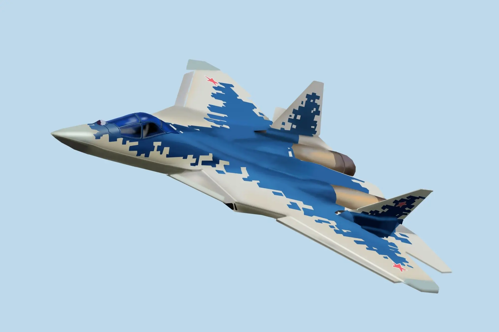
Internal Weapons Carriage - Elimination of External Heat Sources
Internal weapon storage removes external heat sources from missile seeker equipment. Recessed weapons bays maintain smooth thermal surface reducing signature peaks. Enclosed configuration prevents direct infrared exposure of hot missile components. Internal carriage design prioritises thermal signature reduction.
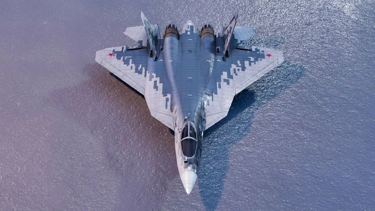
Engine Placement - Fuselage Centerline Positioning
Engines positioned along fuselage centerline enabling optimal shielding geometry. Centerline placement allows fuselage shielding of exhaust plume from lateral threat seekers. Positioning strategy reduces infrared visibility across threat engagement envelope. Design reflects integrated approach to thermal management.
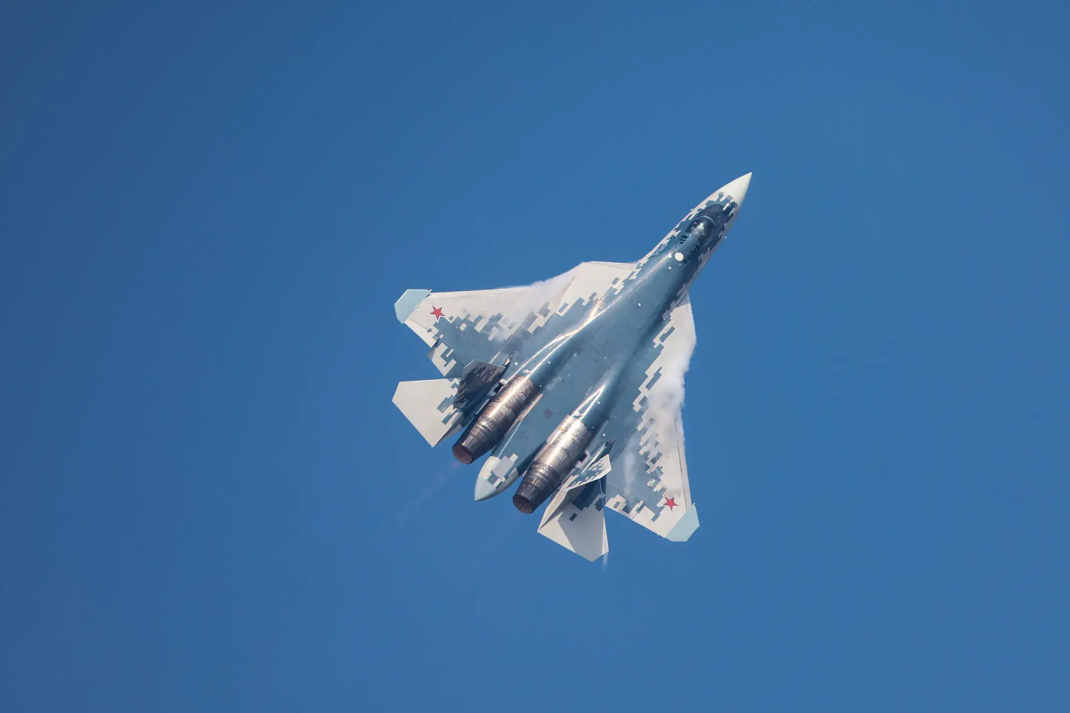
Landing Gear Door Coverage - Thermal Surface Protection
Landing gear doors remain closed during cruise flight preventing hot surface exposure. Closed configuration maintains smooth thermal signature without internal heat leakage. Door design integrates thermal management preventing hot spot visibility. Coverage strategy extends thermal evasion across flight phases.
Bypass Air Circulation - Engine Cooling Integration
Engine bypass air circulation cools external fuselage surfaces reducing thermal differential. Controlled air distribution along airframe minimises detectable temperature peaks. Circulation design balances cooling requirements with infrared reduction objectives. Integration provides sustained thermal suppression capability.
Exhaust Plume Management - Post-Exit Thermal Suppression
Exhaust plume management continues beyond nozzle exit through nozzle geometry design. Plume mixing with ambient air achieves rapid temperature reduction. Design optimisation reduces visible infrared emission during cruise and combat operations. Plume control extends thermal evasion beyond direct engine output.
)
)
)
)
)